- +(91) 7765901124
- sales@akshaymetafab.com

A Comparative Analysis of Conventional Steel Building and Pre-Engineered Building Systems: a case study Approach
Conventional steel building systems typically use truss structures. The structural members that are utilized are hot-rolled and supplied in accordance with the IS code; nevertheless, in many cases, they are heavier than what is actually needed by design. Members maintain a constant cross section regardless of how much the local stresses fluctuate throughout the length of the member. The materials are moved to the location after being manufactured in the plant. Before manufacturing the raw materials are treated on the site to get the required shape and size. Modifications can be done by welding and cutting as the structure is being assembled. Secondary components, which are somewhat heavier, are supplied with standard hot rolled sections.
Through a variety of new goods and services, technological advancement over time has greatly improved people’s quality of life. One such revolution was the Pre-engineered buildings (PEBs). Pre-engineered building concept involves the steel building systems which are predesigned and prefabricated. As the name suggests, this idea entails pre- engineering structural components utilizing a pre-established register of construction materials and manufacturing processes that may be effectively used in compliance with a broad range of structural and aesthetic design requirements. The PEB concept is based on the idea that a section should only be provided at a location if it is necessary there. The bending moment graphic indicates that the sections may change across the length. This results in the use of rigid, non-prismatic frames with thin parts.
For example, tapered I sections made with built-up thin plates are used to achieve this configuration. In pre-engineered building concept, the complete designing and fabrication is done at the factory and the building components are brought to the site in complete knock down condition. These components are then fixed / joined at the site and raised with the help of cranes. The pre-engineered building calls for very fast construction of buildings and with good aesthetic looks and quality construction.Pre-engineered buildings are widely used in the construction of both residential and commercial structures. The PEB concept has shown to be highly effective and well-established in North America, Australia, and is currently spreading throughout the United Kingdom and Europe. PEB construction is 30 to 40% faster than masonry construction. PEB buildings provide a good insulation effect and would be highly suitable for a tropical country like India. PEB is also ideal for construction in remote & hilly areas.
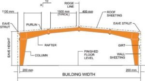
Fig. 1. Main frame cross section

Fig.2 PEB Model
The main objective of this paper is as follows-
The construction industry has witnessed a significant evolution in building technologies, particularly in the shift from conventional construction methods to pre-engineered building (PEB) systems. This review aims to compare these two approaches in terms of design, construction, performance, and sustainability, providing insights into their respective advantages and limitations. Conventional buildings are constructed using traditional methods, with components fabricated on-site based on architectural and engineering drawings. In contrast, PEBs are prefabricated off-site and assembled on-site, often using standardized components that are designed and manufactured in a controlled environment (Al-Asadi et al., 2021).Research suggests that both conventional buildings and PEBs can meet structural requirements. However, PEBs are often lauded for their lightweight design and high-strength materials, allowing for larger clear spans and reduced foundation requirements compared to conventional buildings (Kumar et al., 2018).While the initial cost of PEBs may be higher due to specialized materials and manufacturing processes, studies have shown that they can offer long-term cost savings through reduced construction time and labor costs (Kumar et al., 2018).PEBs have the potential to be more environmentally friendly than conventional buildings due to reduced material waste and energy-efficient design. However, the environmental impact can vary depending on factors such as material sourcing, transportation, and end-of-life considerations (Al-Asadi et al., 2021).
In conclusion, the comparison between conventional building and pre-engineered building highlights the importance of considering project-specific requirements, budget constraints, and sustainability goals. While both approaches have their advantages and limitations,
PEBs offer potential cost and time savings, as well as environmental benefits, making them an attractive option for many construction projects.
We can have a case study to explain the comparison between the conventional building and the pre-engineered building. A building of an industrial structure is considered for design with conventional steel structure and pre-engineered building structure (25m x 52.5m building). The description of the building which is considered for the design purpose is tabulated in table 1
The detailed estimation of the PEB and CSB is done on Excel sheet and actual cost of the project with existing dimensions is found out as a PEB structure. Same dimensions are taken for CSB structure and actual cost is found out. Finally comparison is done between the costs of 2 projects.
Table 1. Description of building for study
Building parameters | ||||
1 | Type of Frame | Clear span | ||
2 | Roof Slope | 1 in 10 | ||
3 | Width (m) | 24.7 m c/c of column | ||
4 | Length (m) | 52.5m c/c of column | ||
5 | Exterior Columns Base Condition | Columns with pinned base condition | ||
6 | Eave -height (M) from FFL | 10.0 m | ||
7 | Bay spacing (m) | 7@ 7.5m c/c of columns | ||
8 | End walls | Right End wall | Frame type: Tapered columns with No Future expansion | Girts: Continuous |
Column Spaces;4@6.175m | ||||
Left End wall | Frame type: Tapered columns with No Future expansion | Girts: Continuous | ||
Column Spaces;4@6.175m | ||||
Building Drawing – The plan & cross section of the building which is considered for the design purpose as shown in fig. no.3
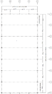
Fig. 3(a) Column Layout Plan
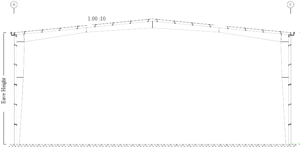
Fig. 3 (b) Cross Section
Cost effectiveness of Pre-engineered Building over conventional building is studied using estimates and also by comparing and calculating the cost of steel quantity of PEB member and conventional steel building member.
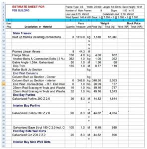
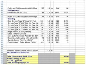
For the above PEB, the estimate was calculated and displayed in the table below:
Table 2. Estimate sheet for PEB
The break up summary sheet of above estimated sheet.
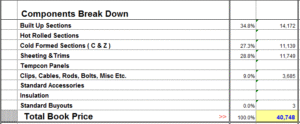
Table 3. Break-up summary sheet for PEB
1) | Quantity of Built-up sections | = 14172 kg |
Rate of Built-up steel | = 52-55 INR per kg | |
Cost of Built-up section | = 14172 X 55 = 779460 INR | |
2) | Quantity of cold formed section | = 11139 kg |
Rate of cold formed steel | = 50-52 INR per kg | |
Cost of cold formed sections | = 11139 X 52 = 579228 INR | |
3) | Quantity of sheeting and trims | = 11749 kg |
Rate of sheeting and trims | = 25.50 INR per kg | |
Cost of sheeting and trims | =11749 X 25.50 = 299599.5 INR | |
4) | Cost of primary, secondary members and sheeting | = 779460+579228+299599.50 = 1658287.50 INR |
5) | Contingencies for clips, cables, rods, bolts, Misc. etc | = 5-8 % of the total cost = 130000 INR |
6) | Total material cost | = 1658287.50 + 130000 = 1788287.50 INR |
7) | Transportation Cost | = 1-2 % of the Material cost = 35500 INR |
8) | Labor rate | = Rs 4-5 per kg |
9) | Total Steel quantity used in Project | = 40748 kg |
10) | Labor cost | = 40748 X 5 =2,03,740 INR |
11) | Overall project cost | = 20,27,527.5 INR |
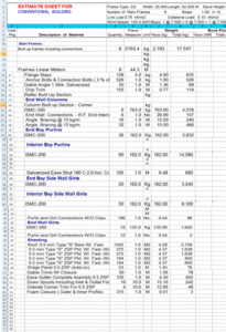
The same above plan was considered for the estimation but as per conventional steel building system. It is tabulated in the table below:
Table 4. Estimate sheet for conventional building system
The break up summary sheet of above estimated sheet which help for comparison of mainframe system & cold form as shown in Table No 3.4
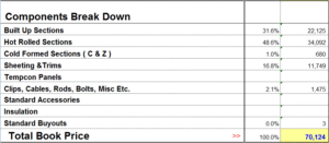
Table 5. Break up summary sheet for conventional steel building
1) | Rate for Built-up sections Quantity of Built-up sections Cost of Built-up sections | = 47 INR per kg = 22125 kg = 22125 X 47 = 1039875 INR |
2) | Rate for hot-rolled section Quantity of hot-rolled steel Cost of hot rolled steel | = 42 INR per kg = 34902 kg = 34902 X 42 = 1465884 INR |
3) | Rate of cold-formed steel Quantity of cold-formed steel Cost of cold-formed steel | = 40 INR per kg = 680 kg = 680 X 40 = 27200 INR |
4) | Rate of sheeting & trims Quantity of sheeting & trims Cost of sheeting & trims | = Rs 25.50 per kg = 11749 kg = 11749 X 25.50 = 299599.50 INR |
5) | Cost of structural members | = 2832558.50 INR |
6) | Cost of contingencies | = 170000INR |
7) | Total material cost | =30,02,558.50INR |
8) | Labour rate | = Rs 5-6 per kg |
9) | Total steel quantity used in Project | = 70124 kg |
10) | Labour cost | = 70124 X 5.5 =4,00,000 INR |
11) | Nominal Transportation Cost | = 15000 INR |
12) | Overall Project Cost | =34,17,558.50 INR |
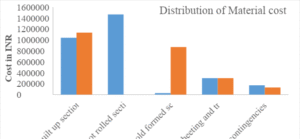
The distribution of Material cost in PEB and conventional steel building is displayed along with the cost savings by PEB as shown in the figure below figure below:
Fig 4. Distribution of material cost obtained from break-up summary
The Material cost in PEB and conventional steel building is calculated from the estimate above and it is compared in the figure below:
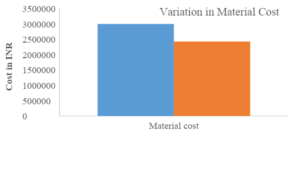
Fig. 5. Cost comparison in Material cost of PEB and conventional steel building
The Transportation cost in PEB and conventional steel building is calculated from the estimate above and it is compared in the figure below:
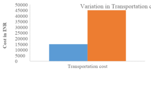
Fig. 6. Cost comparison in transportation cost of PEB and conventional steel building
The Transportation cost in PEB and conventional steel building is calculated from the estimate above and it is compared in the figure below:
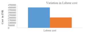
Fig. 7. Cost comparison in labour cost of PEB and conventional steel building
Overall project cost in CSB = 3417558 INR Overall project cost in PEB = 20,27,527.5 INR
Cost savings in PEB project = 3417558.50 – 20,27,527.5
= 13,90,031 INR
Cost-effectiveness in % = (1390031/3417558)*100
= 40.67 %
Journal for Research in Applied Science and Engineering …2021
(5) 2021
…2021
Conventional Steel Buildings (CSB) and Pre-Engineered Buildings (PEB) are the two common approaches to construct steel-framed buildings. This study undertakes a comparison of both PEB and CSB, by focusing on the critical aspect of steel takeoff. Both methods present unique features, challenges and advantages influencing the overall efficiency, sustainability and cost of construction projects. In Conventional steel building construction, components are fabricated on-site whereas, pre- engineered buildings are units of construction in which the components of structure are designed and fabricated off-site with accurate proportions required on-site. After fabricating, the components are transferred to site and fitted using bolted connections [1].
PEB with columns, rafters and purlins is shown in Figure1.
Design and fabrication of the structural units are done under the direction of a quality control officer. The adoptability of PEB by replacing CSB arises in numerous advantages including its economy and quick fabrication. Due to its ductile property steel is earth-quake resistant compared to concrete which is the key reason for increase in steel structures. Under the influence of earthquake forces, the performance of PEB is much better than CSB. It is due to the good structural behaviour and lighter weight of the PEB [1]. Almost in every single feature, PEB gives finer result compared with traditional steel building. The steel buildings are custom-made to have a lighter weight and higher strength. So, the usage of PEB should be adopted more in India as it is eco-friendly.

Figure 1. A typical PEB with Columns, Rafters and Purlins.
Comparison between both structures is based on different parameters of existing Pre-Engineered and Conventional Steel Buildings. Those parameters involve resistance to seismic forces, further expansions, architectural design, accessories of building, software need, usage of codal provisions, and the weight of the overall structure either directly or indirectly. The factors mentioned above play a crucial part in the sustainable construction of structures. Pre-engineered Building shows better solutions in all the factors over Conventional Steel Building [1]. The major problem in structural engineering is safety. In PEB all the precautionary measures are followed by reducing construction rate and time. In future, PEB is going to play a vital role in India [2]. Usage of steel structures is rapidly increased from past few decades. PEB theory was evolved in US, and almost 70% of one- storied buildings at present utilizes pre-engineered structures for non-domestic construction. Up to 1990, PEB was utilized in the Middle east and North America but at present it is utilized in every segment of Asia and Africa [2][3]. PEB design is mostly preferred by contractors and designers for speedy construction and cost-effectiveness.
Cost savings for PEB is nearly 35% compared to CSB[3][4]. In today’s circumstances reducing time and money is increasing their significance in all sectors which include the construction industry. The world is rushing for sustainability. PEB is positioned at the top when differentiated from other technologies in every aspect. The used material for PEB is reusable and biodegradable too. In pre- engineered buildings, steel is the key material among all materials. Steel is a biodegradable material that reflects sustainability. By effectively using high-grade steel and also advanced composite materials the economy of construction in civil can be attained. Traditional steel buildings use steel that is twice as heavy as PEB. The quantity of steel required for the PEB structure is smaller than for the CSB structure [4].
Mainly, the performance relies on the load combination and structural design framework by following Indian and international codes. Pre-engineered building analysis and design will be carried out both manually and with the use of Staad Pro software. The outcome displays how the two codes, using tonnage and deflection criteria, differ from one another. The PEB structure’s design procedure is easy with country standards and its construction is faster, eco-friendly, and sustainable [5]. Reason for increasing in weight using IS 800-2007 is due to additional load combination of wind load than AISC. This is based on detailing and designing [5]. Compared to the Indian Code, AISC code gives economical solution. So, that’s the major priority for adopting AISC codes [5][6].
For distinct spacing of bay and length of span, the AISC code shows 3% to 10% lighter sections than the IS code. This is based on a lower factor of safety of the American code [6]. Deflection limits are lesser for MBMA than IS codes. Because of limiting ratios, IS 800-2007 shows greater weight than AISC/MBMA [7]. The suitable retrofitting technique for the available seismic deficient structures that are not only affordable but also acceptable to stakeholders, owners, and investors is identified. For non-engineered structures, losses can be reduced by 2-11 times and by 3-50 times respectively with the use of proper retrofitting techniques. The huge loss is minimized for steel bracing then after for shear wall and then jacketing [8]. Newly manufactured pre-engineered connection and traditional welded junction are compared in terms of bearing capacity [9].
PEC (Partially Encased Composite Column) is a combination of steel section that is partially outfitted to support a concrete composite column. Tensile strength and ductility are high in steel whereas, fire resistance and compressive strength are high in concrete. So, high strength and stiffness is achieved [10]. Framed beams and columns helps the structure to withstand during earthquake. Repairing the framed structure which is damaged during an earthquake is challenging, and its performance is also poor [11]. Compared to pre-engineered buildings, traditional steel buildings are heavier in weight [12]. Pre-engineered buildings are less expensive when it comes to steel takeoff [12].
The objectives of the present research work are presented below.
A Pre-Engineered Building has been modelled in Staad Pro software. Load calculations have been computed for a 19 m width x 41.1 m length. The geometrical model of the PEB along with the bay spacings in X, Z directions are shown in Figure 2. The columns, rafters and bracings of the PEB are shown in Figures 3 to 5 respectively.
Figure 2. PEB Geometry | Figure 3. Columns of PEB |
Figure 4. Rafters of PEB Figure 5. Bracings of PEB
The properties of PEB columns are shown in Table 1. The properties of end and middle rafters (Rafter-1, 2) are shown in Table 2. The properties of cross-bracings of PEB are shown in Table 3.
Table 1. Description of PEB columns
Properties of column | Dimensions of column (m) |
Depth at the start node | 0.2 |
Web thickness | 0.005 |
Depth at the end node | 0.6 |
Top flange width | 0.2 |
Top flange thickness | 0.010 |
Table 2. Description of PEB rafters
Properties of Rafter | Dimensions of Rafter-1 (m) | Dimensions of Rafter-2 (m) |
Depth at the start node | 0.55 | 0.2 |
Web thickness | 0.005 | 0.005 |
Depth at the end node | 0.2 | 0.15 |
Top flange width | 0.25 | 0.25 |
Top flange thickness | 0.010 | 0.010 |
Table 3. Description of bracings and cross-bracings of PEB
Description of the element | Type | Material |
Eave strut | PIP483L | Steel |
Cross bracings at end frame | PIP761L | Steel |
Cross bracings at middle frame | PIP483L | Steel |
The properties columns, rafters, eave strut and cross-bracings used in CSB are shown in Table 4.
Table 4. Description of CSB elements
Description of the element | Type |
Column 1 | ISWB 400 |
Column 2 | ISWB 350 |
Rafter 1 | ISWB 450 |
Rafter 2 | ISWB 350 |
Eave strut | PIP 483 L |
Cross bracings at end frame | PIP 761 L |
Cross bracings at middle frame | PIP 424 L |
Wind load acting on PEB at angles θ=00, 900, 1800 and 2700 are calculated as per IS 875 (Part III) and tabulated in Tables 5 & 6.
Table 5. Wind load on members with internal pressure coefficient Cpi= + 0.2
Member | WL – Left θ=00 (kN/m) | WL – Right θ=1800 (kN/m) | WL – Top θ=900 (kN/m) | WL – Bottom θ=2700 (kN/m) |
A | 1.919 | -1.727 | -2.687 | -2.687 |
B | 1.727 | -1.919 | 2.687 | 2.687 |
C | -3.54 | -3.54 | 2.22 | -1.33 |
D | 3.54 | 3.54 | 1.33 | -2.22 |
EF | 3.41 | 1.86 | – | – |
GH | 1.86 | 3.41 | – | – |
EG | – | – | 3.11 | 1.86 |
FH | – | – | 1.86 | 3.11 |
A (corner columns) | 0.959 | -0.863 | -1.343 | -1.343 |
B (corner columns) | 0.863 | -0.959 | 1.343 | 1.343 |
C (corner columns) | -1.77 | -1.77 | 1.11 | -0.66 |
D (corner columns) | 1.77 | 1.77 | 0.66 | -1.11 |
EF (corner rafters) | 1.71 | 0.93 | – | – |
GH (corner rafters) | 0.93 | 1.71 | – | – |
EG (corner rafters) | – | – | 1.55 | 0.93 |
FH(corner rafters) | – | – | 0.93 | 1.55 |
Table 6. Wind load on members with internal pressure coefficient Cpi= – 0.2
Member | WL – Left θ=00 (kN/m) | WL – Right θ=1800 (kN/m) | WL – Top θ=900 (kN/m) | WL – Bottom θ=2700 (kN/m) |
A | 3.45 | -0.191 | -1.151 | -1.151 |
B | 0.191 | -3.45 | 1.151 | 1.151 |
C | -1.77 | -1.77 | 3.98 | -0.44 |
D | 1.77 | 1.77 | 0.44 | -3.98 |
EF | 2.17 | 0.62 | – | – |
GH | 0.62 | 2.71 | – | – |
EG | – | – | 1.86 | 0.621 |
FH | – | – | 0.621 | 1.86 |
A (corner columns) | 1.727 | -0.095 | -0.575 | -0.575 |
B (corner columns) | 0.095 | -1.727 | 0.575 | 0.575 |
C (corner columns) | -0.88 | -0.88 | 1.99 | -0.22 |
D (corner columns) | 0.88 | 0.88 | 0.22 | -1.99 |
EF (corner rafters) | 1.08 | 0.31 | – | – |
GH (corner rafters) | 0.31 | 1.08 | – | – |
EG (corner rafters) | – | – | 0.93 | 0.31 |
FH (corner rafters) | – | – | 0.31 | 0.93 |
Site location : Hyderabad
Zone factor : 0.1
Importance factor (I) : General building
Damping ratio (DM) : 0.05
Type of structure (ST) : Steel frame building
Response reduction Factor (RF) : Special RC moment resisting frame Rock and soil site factor (SS) : Medium soil
Live loads acting on middle and end rafters are shown in Figures 6, 7 and Wind loads with internal pressure coefficients +0.2 acting on Pre-Engineered building are shown in Figures 8 to 11 respectively.

Figure 6. LL acting on middle rafters
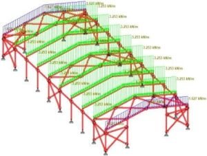
Figure 7. LL acting on end rafters

Figure 8. WL-Left at angle θ = 00 & +0.2 Cpi

Figure 9.WL-Right at angle θ = 1800 & + 0.2 Cpi
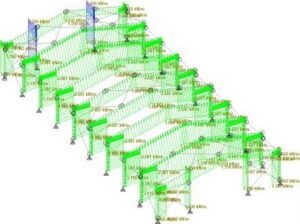
Figure 10. WL-Top at angle θ = 900 & +0.2 Cpi
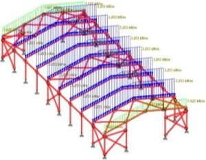
Figure 11. WL-Bottom at angle θ = 2700 &+ 0.2 Cpi
Maximum bending moment and shear forces of PEB are shown in Figures 12 to 13. The maximum
bending moment and shear forces of CSB are shown in Figures14 to 15
Figure 12. The maximum BMD of PEB | Figure 13. The maximum SFD of PEB |
Figure 14. The maximum BMD of CSB | Figure 15. The maximum deflection of CSB |
The PEB and CSB are analysed for 74 different load combinations as per the IS codes. The results obtained from the analysis are tabulated in Tables 7 and 8.
Table 7. Steel take-off for PEB
S.No. | Profile | Length (m) | Weight (kN) |
1 | Tapered Member No:1 | 92.40 | 41.89 |
2 | Tapered Member No:2 | 19.81 | 9.36 |
3 | Tapered Member No:3 | 102.91 | 53.18 |
4 | Tapered Member No:4 | 91.98 | 40.80 |
5 | PIP 761 L | 208.97 | 11.77 |
6 | PIP 483 L | 76.66 | 2.44 |
7 | PIP 1143 L | 102.20 | 9.81 |
Total : | 169.25 |
Table 8. Steel take-off for CSB
S.No. | Profile | Length (m) | Weight (kN) |
1 | ISWB 400 | 92.40 | 60.33 |
2 | ISWB 350 | 111.79 | 62.26 |
3 | ISWB 450 | 102.19 | 79.29 |
4 | PIP 761 L | 208.97 | 11.77 |
5 | PIP 424 L | 76.66 | 1.91 |
6 | PIP 1143 L | 102.20 | 9.81 |
Total : | 225.37 |
Table 9. Analysis results of PEB and CSB
S.No. | Parameter | PEB | CSB | % change |
1 | Maximum bending moment (kN-m) | 189.56 | 171.61 | 9.46 % |
2 | Maximum shear force (kN) | 52.43 | 56.20 | 6.70 % |
3 | Maximum axial force (kN) | 65.77 | 70.60 | 6.83 % |
4 | Maximum support reaction (kN) | 67.02 | 71.52 | 6.29 % |
The results of PEB are compared with that of CSB and the quantity of steel required for Pre- engineered building is reduced by 24.90 % compared to CSB. Thus, the cost of PEB is reduced considerably. For eave struts and cross bracings, same pipe sections are used. When compared both seismic and wind load analysis, wind load combinations are found to be critical.
PEB and CSB were analyzed for various load combinations and results obtained from the analysis were presented in Table 9. The maximum BM, maximum SF, maximum AF and maximum support reactions are presented in Table 9.
Two typical steel buildings, one with PEB sections and the other with CSB sections available from steel tables have been designed for various load combinations.
1197:012086.https://doi.org/10.1088/1757-899X/1197/1/012086
(IRJET). 8(5):2395-0056.
Kiran GS, Rao AK, Kumar RP. 2014. Comparison of design procedures for pre-engineering buildings (PEB): a case study. International Journal of Civil, Architectural &Construction Engineering(IJCASCE).8(4):477-81.
Technical specification of Pre- Engineered Building
SPECIFICATIONS :
Commissioning at Site of Pre-engineered Steel Structure, furnishing of design, working drawings, calculations, data sheets, records and getting the same approved from the Owner / Consultant, testing and quality assurance, inspection and quality checks complete. The Scope of Pre-engineered Steel Structure includes various components of structural steel sections, internal including all fittings / fixtures like purlins, flashing, bracing & Anchor Bolts, Nuts, Washer, permanent bolts with templates etc. complete.
Architectural drawings including preparation Animated Computer model in 3D Max.
However the fabrication of the structure is to be started only after approval of the “Good for Construction” drawings.
IS Code Practice for General Construction in Steel : (IS:800-2007) IS Code Practice for Hot rolled sections and plates : (IS:2062)
IS Code of Practice for Cold Form : (IS:801-1975)
IS Code of Practice for Design Loads Part-3 : (IS:875-1987) IS Code of Practice for Earth Quake Loads Part-1 : (IS:1893-2002) American Welding Society Specification : (AWS D1.1.98)
American Institute of steel construction : (AISC)
Metal building manufactures association : (MBMA) Manual of steel construction, 9th edition
The 1996 edition of low rise building system manual.
4.6 (part 1 to 3).
Live Load
Live Load on roof and frame shall be 0.75kN/m^2 as per IS-875 Part-2
Dead load
Dead load on roof shall be min. 0.15kN/m^2
Earthquake load
As per IS 1893 (Part-1) – 2002.
Importance Factor & Response reduction as per IS 1893 Part IV.
Wind load as per IS 875 Part 3, 1987
Other Loads
Design of all structures shall also consider any other relevant stresses imparted to the structure due to variation in daily and seasonal temperature, water label, erection and maintenance loads, creep shrinkage etc.
Wind and seismic forces shall not be considered to act simultaneously.
Individual members of the frame shall be designed for the worst combination of forces such as bending moment, axial force, shear force, torsion etc. resulted from the most critical combinations of loads as specified below.
1.5* Dead Load + 1.5* Live / Imposed Load
1.5* Dead Load + 1.5* Live / Imposed Load + 1. 5* Piping/Fire fighting Load
1.5* Dead Load + 1.5* (Wind / Seismic Load) 0.9* Dead Load + I.5*(Wind / Seismic Load)
1.2* Dead Load + 1.2* Live/Imposed Load + 1.2* Piping/Fire fighting + 1.2* (Wind / Seismic load)
Service load combinations for general buildings shall be: 1.0* Dead Load + 1.0* Live/Imposed Load
1.0* Dead Load + 1.0* Live/Imposed Load 1.0* Piping/Fire fighting Load
1.0* Dead Load + 1.0* (Wind/ Seismic Load)
1.0* Dead Load + 1.0* Piping/Fire fighting Load + 0.8*(Wind/ Seismic Load)
1 .0 * Dead Load + 0.8* Live/Imposed Load + 0.8* Piping/Fire fighting Load + 0.8*(Wind/ Seismic Load)
Permissible stresses for different load combinations shall be taken as per relevant IS Codes.
Angle/Rod bracing for roof and wall is considered.
Main frame column base considered as pinned support.
Built up & Hot rolled sections to be designed as per Manual of Steel Construction, 9th edition, American Institute of Steel Construction (AISC) & IS: 800.
Cold formed members to be designed as per 1996 Edition of Cold-Formed Steel Design Manual, American Iron and Steel, Institute (AISI), IS: 801&
IS: 513.
Welding shall be applied in accordance with: American Welding Society (AWS D1.1.98) Structural Welding Code – Steel. IS: 800, IS: 813 & IS: 816.
The permissible vertical deflection for structural steel members shall be as specified below:
Steel Structure simple span Beam shall be Span / 240.
Steel Structure for cantilever span Beam shall be Span / 120.
Permissible horizontal displacement at crane level / eaves level shall be Height / 150.
Permissible Deflection for Purlin shall be Span / 150. Permissible Deflection for Side Runner Shall be Span / 150
Permissible Deflection for Chequered Plate/Grating shall be Span / 200 or 6 mm, whichever is lower.
The Contractor shall adopt suitable quality assurance plan to ensure that materials and services under the scope of contract, whether manufactured or performed within the contractor’s works or at the owner’s site or at any other place of work are in accordance with the specifications. Such Plan shall be outlined by the contractor and shall be finally accepted by the owner/ consultant. QAP shall be submitted to owner/consultant for review and comment. Hard copies of final quality plans shall be submitted for stamping and approval.
Manufacturing Quality Plan (MQP) will detail out for all the components, various test/ inspection, to be carried out as per requirement of this specification and standard mentioned therein and quality practices and procedures followed by contractor’s Quality Control Organization, the relevant reference documents and standards, acceptance norms etc. during all stages of manufacturing including raw material procurement, in-process manufacturing, assembly, and final testing.
Field Quality Plans (FQP) will detail out for all the equipment, the quality practices and procedures etc. To be followed by the contractor’s “Site Quality Control Origination “, during various stage of site activities.
DRAWINGS
Surface Preparation: The surfaces to be painted shall be shot blasted as per SAE 2.5.
The following specification shall be used for painting of structural steel work.
Painting for structural members shall be one or more coat of Red Oxide primer and 2 or more coats of Synthetic Enamel Paint of approved brand having thickness of 90-100 micron DFT at site.
provide all necessary arrangements and assistance, which the Owner / Consultant may require for checking the setting out.
3.5 mm on each 10 M. Section of height and not more than 7.0 mm per 30 meter section. These tolerances shall apply to all parts of the structure unless mentioned in the drawings issued for erection purposes.
The Ultimate Guide to Pre-Engineered Buildings (PEB) & Steel Structures: Design, Components, and Advantages
Introduction: Why Pre-Engineered Buildings (PEB) Are Shaping Modern Construction In the evolving world of construction, businesses across industries demand faster, cost-effective, and sustainable building solutions. Traditional methods involving brick, mortar, and RCC are often slow, labor-intensive, and difficult to modify later.
This is where Pre-Engineered Buildings (PEB), also known as steel buildings, modular or prefabricated buildings, come into play. Leveraging advanced construction technologies, structural steel, and modular design, PEB systems are revolutionizing how we build industrial buildings, warehouses, manufacturing facilities, retail outlets, schools, hospitals, and even community centers.
What Are Pre-Engineered Buildings (PEB)?
A Pre-Engineered Building is a steel structure system that’s designed, fabricated, and quality-checked in a factory-controlled environment, then shipped to the site in
ready-to-assemble kits. This approach ensures:
1. Precision-engineered design
2. Superior structural integrity & durability
3. Rapid on-site installation (erection)
4. Reduced labor and minimal material wastage.
Where Are PEB Systems Used?
PEBs have become the go-to solution across multiple sectors due to their flexibility and robustness. Typical applications include:
Industrial: Warehouses, Factories & workshops, Manufacturing plants, Cold storage facilities, Petrochemical & power plants, Food processing facilities.
Commercial: Retail showrooms & shopping complexes, Office buildings, Exhibition halls.
Institutional & Public: Schools & colleges, Hospitals, Community centers, Sports arenas
Agricultural: Storage barns, Dairy facilities, Poultry farms.
Special structures: Aircraft hangars, Car parks, Logistics hubs.
The Key Components of a PEB Structure
A well-designed PEB integrates multiple systems:
Primary Members
Columns & Rafters (Portal Frames): Often with tapered design to use material efficiently.
Gable Frames & End Frames: Provide rigidity and shape.
Secondary Members
Purlins & Girts: Support roof & wall panels. Often made from cold-formed steel.
Eave Struts, Bracings, Sag Rods: Ensure structural stability.
Base Plates & Anchor Bolts: Connect the structure to the foundation.
Roof & Wall Systems
Roof Panels & Wall Panels: Typically metal sheets or sandwich panels with insulation.
Ridge Caps, Gutters, Downspouts: Manage rainwater.
Flashing: Seals edges & joints to prevent leaks.
Interior & Accessories
Doors, Windows, Louvers, Skylights: For light, air, and access.
Mezzanine Floors: Adds interior levels.
Crane Systems: Integrated for industrial operations.
Materials & Structural Steel in PEB
Types of Steel Used
Steel Grade Yield Strength Use Cases
E250A / E250BR ~350 MPa General framing, light to medium industrial
E350 ~550 MPa Heavy-duty industrial, crane systems.
PEB structures typically use:
Hot-rolled steel: For primary built-up members (columns, rafters)
Cold-formed steel: For secondary members like purlins, girts
Galvanized / Pre-galvanized: For corrosion protection
Special coatings (e.g. Burger paints) for longer life
Key Properties
Formability & weldability: Essential for fabrication & complex profiles.
Corrosion resistance: Extended life in harsh environments.
Fire & seismic resistance: Designed as per local codes.
Engineering Standards & Design Codes
PEB manufacturers adhere to strict international and local codes for safety and performance:
IS:800: Indian Standard for general steel design
AISI: Design of cold-formed steel structures
AWS D1.1: Welding standards for structural steel
Also considers:
Wind load, snow load, live load, dead load, seismic load
Material specifications & steel grade certifications
Fabrication, Quality & Construction Process
1. Design Engineering
Using 3D Modeling & BIM (Building Information Modeling) to ensure clash-free, optimized designs.
2. Factory Fabrication
Cutting, forming, welding, assembly: Controlled for precision.
Built-up members (columns, rafters) use hot-rolled plates welded into I-sections.
Secondary members like purlins, girts use cold-formed C/Z sections.
3. Quality Control & Testing
Dimension checks, welding tests, material certification, paint thickness checks.
4. On-Site Installation (Erection)
Delivered as a kit. Bolted together on pre-prepared foundations using anchor bolts, guided by design drawings.
Advantages of PEB Over Traditional Construction
Benefit Traditional RCC PEB Steel Structures
Speed Slow (12-18 months) Fast (4-6 months)
Cost Control Often overruns Predictable, fixed pricing
Quality Inconsistent Factory-controlled precision
Flexibility Difficult to expand Easy to extend or relocate
Sustainability Waste intensive Recyclable steel, minimal waste
Maintenance Cracks, damp Minimal, easy repaint & inspect.
Special Types of Steel Buildings
Clear Span Buildings: Large unobstructed interiors for aircraft hangars, sports stadiums.
Multi-Span Buildings: Large factories requiring multiple frames.
Single Slope & Portal Frames: For efficient water drainage & simplicity.
Low-Rise Buildings: Typical for most PEB.
Hybrid solutions for limited high-rise: Combining PEB with RCC for up to 10+ floors.
Case Study: PEB in Action
Project: Cold Storage & Processing Facility
Size: 30,000 sq ft
Structure: Clear span with mezzanine, integrated crane system
Steel: E350 grade primary, cold-formed secondary
Completion: 5 months (vs 12 with RCC)
Results: Early operation, saved 30% on project costs, reduced energy needs via insulated panels.
Conclusion: Why PEB is the Smart Choice
Whether you’re planning a warehouse, factory, hospital, or retail outlet, a PEB system delivers unmatched speed, cost efficiency, quality, and sustainability. By working with reputable PEB manufacturers & suppliers, you ensure compliance with international codes, superior fabrication quality, and long-term performance.
Short FAQs
What is a Pre-Engineered Building (PEB)?
A building fully engineered at a factory, fabricated with steel members, and assembled on-site for faster, higher quality construction.
What are PEB structures typically used for?
Warehouses, factories, cold storage, showrooms, hospitals, schools, aircraft hangars, and agricultural facilities.
How long does a PEB building take to complete?
Usually 30-50% faster than traditional RCC construction. Many projects complete in 4-6 months.
Is it possible to expand or modify PEB structures later?
Yes. PEBs are modular—easy to extend, relocate, or retrofit.
What standards are followed in PEB design?
IS:800, AISI for cold-formed, AWS D1.1 for welding, plus local wind, seismic, and fire codes.
How is steel protected from rust?
Via galvanizing, specialized paint systems, and quality controlled fabrication.
What’s the difference between hot-rolled and cold-formed steel?
Hot-rolled is used for heavy primary frames; cold-formed for lighter secondary members like purlins and girts.